Power-over-ethernet diagrams
From Fab Lab Wiki - by NMÍ Kvikan
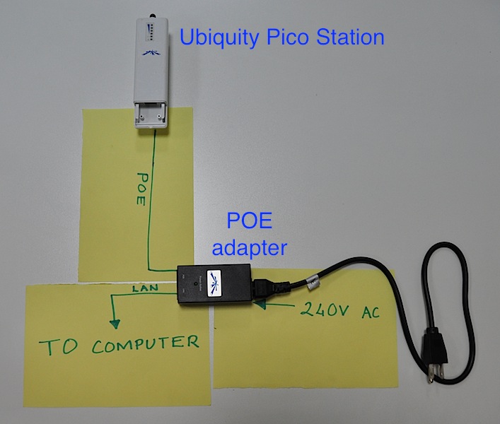
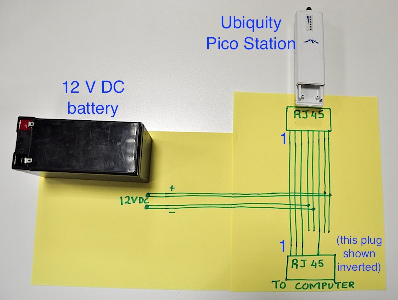
A collection of diagrams showing how to connect power over ethernet to ubiquity devices laid out in various topographies and power sources.
These were made by Tom Okite, Hansel Omondi and Laurence Ombuki from ARO FabLab Kenya West.
UPDATE - DO NOT FOLLOW THE INSTRUCTIONS GIVEN FOR THE DC WIRING DIAGRAM!! THEY ARE INCORRECT. IF YOU WIRE AS SHOWN (LIKE I DID) YOU WILL REVERSE POLARITY AND MOST LIKELY DESTROY YOUR DEVICE. THE CORRECT WIRING IS THE OPPOSITE OF THAT SHOWN IN THE DIAGRAM. IE. BLUE PAIR IS POSITIVE. BROWN PAIR NEGATIVE.
Single Ubiquity Device
In the following two diagrams, we are connecting one Ubiquity device. When using AC power we must use an AC POE adapter. When using 12 V DC power we can simply branch off the wires which connect to the battery.

