HiKnitterStream: Difference between revisions
Soldering |
|||
| (10 intermediate revisions by 2 users not shown) | |||
| Line 1: | Line 1: | ||
== Day 1 (02.10.2014) == | == Day 1 (02.10.2014): Looking inside == | ||
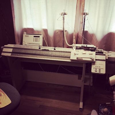
Dissembled and reassembled PASSAP E6000. Found out some things can be disconnected beforehand, making it easier for transportation later on. Lesson learned: read the manual! | Dissembled and reassembled PASSAP E6000. Found out some things can be disconnected beforehand, making it easier for transportation later on. Lesson learned: read the manual! | ||
[[File:hiKnitterStream_Machine.jpg|400px]] | |||
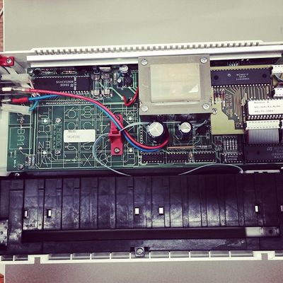
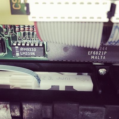
Managed to open the E6000 console. Turns out the hardware is exactly the same (serial no. 05.351.05.4.02) as used in the original KnitterStream. Software is probably an older version (dated 01.11.1993) and the pattern-reading scanner (?) is from 23.09.1994 -- in summary, some 20 year old hard- and software. | Managed to open the E6000 console. Turns out the hardware is exactly the same (serial no. 05.351.05.4.02) as used in the original KnitterStream. Software is probably an older version (dated 01.11.1993) and the pattern-reading scanner (?) is from 23.09.1994 -- in summary, some 20 year old hard- and software. | ||
[[File:hiKnitterStream_CircuitBoard.jpg|400px]] | |||
Started going through the code on [https://github.com/borgstrom/KnitterStream github] by [https://twitter.com/EvanBorgstrom Evan Borgstrom] and [https://twitter.com/isharko Ivan Sharko]. Never having done any 'physical' computer programming before, the learning curve is a bit steep. However looking at the [http://www.moveplaycreate.com/blog/post02_Knitterstream/hacking.jpg instagram photo] attached to the creators' [http://play.moveplaycreate.com/post/44786499875/hacking-away blog post] the penny finally dropped. Each constant in the code represent a button on the console, and it's ''just'' a matter of soldering some insane amounts of wires (sounds daunting, but doable) onto the arduino board. | Started going through the code on [https://github.com/borgstrom/KnitterStream github] by [https://twitter.com/EvanBorgstrom Evan Borgstrom] and [https://twitter.com/isharko Ivan Sharko]. Never having done any 'physical' computer programming before, the learning curve is a bit steep. However looking at the [http://www.moveplaycreate.com/blog/post02_Knitterstream/hacking.jpg instagram photo] attached to the creators' [http://play.moveplaycreate.com/post/44786499875/hacking-away blog post] the penny finally dropped. Each constant in the code represent a button on the console, and it's ''just'' a matter of soldering some insane amounts of wires (sounds daunting, but doable) onto the arduino board. | ||
It looks like to make room for the arduino components, the punch-card scanner device must go out. Not wanting to lose that retro feature, the plan is to try something less intrusive. Perhaps make a circuit board from scratch, thereby making full use of the FABLAB facilities. Before doing that, I'd need more information about what the creators of KnitterStream were actually doing, a) how is everything connected? b) where are the analog pins located on the board? c) and what's their function? d) what's the motor part doing, i.e., what does M1_PWM and M1_DIR stand for? And if all possible, try to obtain a schematic of pictures of the process. | It looks like to make room for the arduino components, the punch-card scanner device must go out. Not wanting to lose that retro feature, the plan is to try something less intrusive. Perhaps make a circuit board from scratch, thereby making full use of the FABLAB facilities. Before doing that, I'd need more information about what the creators of KnitterStream were actually doing, a) how is everything connected? b) where are the analog pins located on the board? c) and what's their function? d) what's the motor part doing, i.e., what does M1_PWM and M1_DIR stand for? And if all possible, try to obtain a schematic of pictures of the process. | ||
== Day 2 (06.10.2014): Hardware breakdown notes == | |||
Mainboard | |||
* [http://www.datasheets360.com/pdf/-1360389224796280150 KM62256BLP-8 322C] (located under controller breakout board | |||
* [http://pdf.datasheetcatalog.com/datasheets2/15/150901_1.pdf S9406 MM58341N] | |||
* Program A 05.363.43.4.06 01.11.1993 [https://en.wikipedia.org/wiki/EPROM EPROM] under breakout board | |||
* [http://www.datasheetarchive.com/dlmain/Datasheets-8/DSA-151005.pdf S22TD 9344 EF6821P MALTA] | |||
* [http://www.datasheetarchive.com/dlmain/Datasheets-8/DSA-151004.pdfS22ZA 9348 EF6809P MALTA] | |||
Small chips | |||
* DM74LS165 P9336 | |||
* 3191DKK 74LS05N | |||
* LM339N M9330 | |||
* 3316U1K SN74LS393N | |||
* 3324SVK SN74S10N | |||
* 248 4 T F K SN74LS04N | |||
Breakout Board | |||
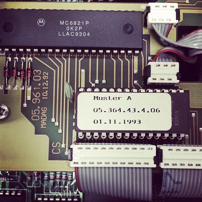
* MC6821P 0K2P LLAC9304 | |||
* Muster A 05.364.43.4.06 01.11.1993 | |||
We've discovered several controller chips on the main board of the knitter | |||
[[File:hiKnitterStream_CircuitBoardMusterA.jpg|400px]][[File:hiKnitterStream_CircuitBoardMalta1994.jpg|400px]] | |||
== Day 3 (07.10.2014): Documentation diving == | |||
Looks like we've struck gold! [http://www.offthestreet.net/index.php?N=0202 WinCrea] is FreeWare that allows a computer to interact with the PASSAP E6000 via a cable. Most importantly, looking at the source code (briefly) there seems to be documentation on the cable wiring. A standard Creation 6 cable, with dongle (whatever that means), can be used. Followed by instructions of what kind of connectors are needed an where specific pins are located (I think). By the looks of it, the cable circumvents the using the console by using the DIN connector from the back of the console to connect to a COM connector on a computer. However, how can that be used in conjunction with the motor control which connects the E6000 to the 4600 motor. Perhaps there are some schematics for how to create your own Standard Creation 6 Cable, e.g., a proper schematic that isn't a drawing using textwriter font! | |||
Moreover, there is also a more commercial plug-and-play option out there, [https://www.softbyte.co.uk/designaknit.htm DesignaKnit8] by SoftByte. The [https://www.softbyte.co.uk/cablelinkspassap.htm cable] needed is chip dependent, so in case if the serial number of the console is lower than 6025980, it will need some chips replacing -- however our E6000 has serial number 7041398 (C.S. 4369N), so it should be compatible. But what's the fun in that? | |||
I found these links by reaching out to a the facebook group [https://www.facebook.com/groups/PassapKnitting Ruth's Passap Machine Knitting] which were more than helpful sharing documentation. So all possible official manuals from PASSAP, both for E6000 and its predecessor DUO80, are just one click away. | |||
Similar hacker projects | |||
* [https://www.hackerspace-bamberg.de/Passap_pfaff_e6000 Backspace/Hackerspace] (in German) - which is based on the WinCrea freeware. Seems to have gotten rid of the console, and automatic calibration (i.e. not set the start position). Warning, some of my understanding might have been lost in Google-translation. | |||
* [http://borgstrom.ca/2012/05/06/hacking-the-passap-e6000-knitterstream.html KnitterStream] - affectionately referred to turning a thoroughbred into a one trick pony within the PASSAP E6000 community. Well, if that's the case, it's a ''very'' cool one trick pony. | |||
== Day 4 (10.10.2014): Swatching == | |||
Tried following the instructional from [https://www.youtube.com/watch?v=WPXsENIwo-A YouTube]. Surprisingly, it's a little too fast-paced, so I didn't complete it on this visit. But here are some notes. | |||
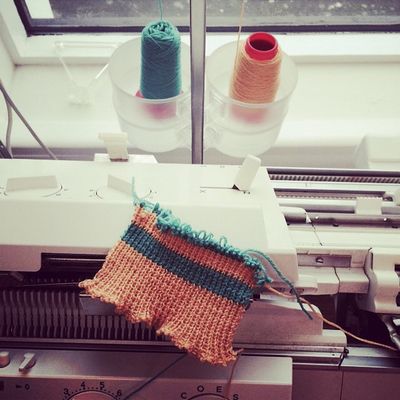
First off, had some difficulty with the Auto-Color, it released the color too late (i.e. on the other side of the knitting apparatus). Managed to do some two-color ribbing (apologies for the color pallette): | |||
[[File:hiKnitterStream_FirstSwatch.jpg|400px]] | |||
Note to self: To get rid of that annoying ERROR beep simply click 'Enter' (duh!) -- there's not need to panic and turn off the console completely. | |||
Small fix of the day: Jason super-glued together the yarn catcher that broke during transport. | |||
== Day 5 (14.10.2014): Cable Connections == | |||
I contacted a couple of Passap E6000 experts I found scavenging PASSAP forums for clues on how to hack the machine. | |||
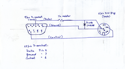
I got a diagram of the cable connections from Chris Dixon, who is the creator of the WinCrea freeware. Included in the [http://www.offthestreet.net/index.php?N=0202 source code] download bundle is a manual. In the last section there is some rough how-to for making your own cable. Let's just say, a picture says more than a thousand words! | |||
[[File:hiKnitterStream_WinCreaDINdiagram.png|400px]] | |||
Note, [http://www.vishay.com/docs/81857/1n4148.pdf Diode 1n4148] and a 1K resistor (quarter watt) were not included in the original cable specification for WinCrea, but added as safety measure. | |||
Richard Croucher, has been most generous. Thanks to him we have all sorts of valuable information, which we are still working through. He is an experienced electronic design engineer, so it's safe to say he really knows what he's talking about (fyi: he suggested the safety adjustments for the WinCrea cable). With the documentation he gave us, it looks like we have all the information we need to get ourselves on track. All from chip and cable specifications to general limitations of the machine. | |||
== Day 6 (13.11.2014): Shopping for supplies == | |||
Back from vacation. Got the console from FabLab, went to Miðbæjar Radíó for buying parts to make a DIN-6 cable. Got 2-females and 1 male component, along with 1m 7fold cable to go with it. | |||
== Day 7 (17.11.2014): Soldering is Easy == | |||
First time soldering! I suggest any novice prints out [http://log.andie.se/post/397677855/soldering-is-easy Andie Nordgren]'s ''Soldering is Easy'' [http://log.andie.se/post/4529161438/soldering-is-easy-the-comic-book Comic booklet] or [https://skitch-img.s3.amazonaws.com/20100219-pmcq2auhgiwj1imwd2p8rg8sju.jpg 1-page handout]. Just remember to watch your hands afterwards (otherwise you lose all your friends!) and be careful of not touching the soldering iron, it's heated to 300°C. | |||
[[File:hiKnitterStream_SolderingStation.jpg|250px]] | |||
First we expose the wires from the cable, and pretin each one. Next we pretin the connectors. As there are 7 wires in the cable, and only 6 on the DIN connector, the last wire is connected to the backside of the connector. I started with the female, then the color order didn't really matter -- the wires just had to sit nicely. For the male, they had to be in the exact same order as the female. Hence, the color-encoding scheme: | |||
* 1) White | |||
* 2) Pink | |||
* 3) Blue | |||
* 4) Grey | |||
* 5) Yellow | |||
* 6) Brown | |||
* 7) Green (outside) | |||
Note to self, soldering is NOT painting! The soldering iron should stay in one place (kind of), but the actual solder should rather move -- not the other way around. Also, I noticed it was usually considerably easier to solder wires next to the connectors, rather than through or on top of them. Once the connecter is all set, the metal/plastic casing is put in place and we check if each connection is being sent to the correct connection on the opposite side. | |||
[[File:hiKnitterStream_DIN6_pretinned.jpg|250px]] | |||
[[File:hiKnitterStream_DIN6_pins.jpg|250px]] | |||
[[File:hiKnitterStream_DIN6_insideConnected.jpg|250px]] | |||
[[File:hiKnitterStream_DIN6_outsideConnected.jpg|250px]] | |||
Now, we cut the cable in two halves. Connected each side to a comb (?) that will be later connected onto a breadboard, so we can eaves-drop what is being sent from the machine to the console. | |||
[[File:hiKnitterStream_DIN6_combs.jpg|250px]] | |||
[[File:hiKnitterStream_DIN6_combConnected.jpg|250px]] | |||
[[File:hiKnitterStream_DIN6_workingCable.jpg|250px]] | |||
[[Category:Projects]] | [[Category:Projects]] | ||
[[Category:Electronics]] | [[Category:Electronics]] | ||
Latest revision as of 10:03, 18 November 2014
Day 1 (02.10.2014): Looking inside
Dissembled and reassembled PASSAP E6000. Found out some things can be disconnected beforehand, making it easier for transportation later on. Lesson learned: read the manual!
Managed to open the E6000 console. Turns out the hardware is exactly the same (serial no. 05.351.05.4.02) as used in the original KnitterStream. Software is probably an older version (dated 01.11.1993) and the pattern-reading scanner (?) is from 23.09.1994 -- in summary, some 20 year old hard- and software.
Started going through the code on github by Evan Borgstrom and Ivan Sharko. Never having done any 'physical' computer programming before, the learning curve is a bit steep. However looking at the instagram photo attached to the creators' blog post the penny finally dropped. Each constant in the code represent a button on the console, and it's just a matter of soldering some insane amounts of wires (sounds daunting, but doable) onto the arduino board.
It looks like to make room for the arduino components, the punch-card scanner device must go out. Not wanting to lose that retro feature, the plan is to try something less intrusive. Perhaps make a circuit board from scratch, thereby making full use of the FABLAB facilities. Before doing that, I'd need more information about what the creators of KnitterStream were actually doing, a) how is everything connected? b) where are the analog pins located on the board? c) and what's their function? d) what's the motor part doing, i.e., what does M1_PWM and M1_DIR stand for? And if all possible, try to obtain a schematic of pictures of the process.
Day 2 (06.10.2014): Hardware breakdown notes
Mainboard
- KM62256BLP-8 322C (located under controller breakout board
- S9406 MM58341N
- Program A 05.363.43.4.06 01.11.1993 EPROM under breakout board
- S22TD 9344 EF6821P MALTA
- 9348 EF6809P MALTA
Small chips
- DM74LS165 P9336
- 3191DKK 74LS05N
- LM339N M9330
- 3316U1K SN74LS393N
- 3324SVK SN74S10N
- 248 4 T F K SN74LS04N
Breakout Board
- MC6821P 0K2P LLAC9304
- Muster A 05.364.43.4.06 01.11.1993
We've discovered several controller chips on the main board of the knitter
Day 3 (07.10.2014): Documentation diving
Looks like we've struck gold! WinCrea is FreeWare that allows a computer to interact with the PASSAP E6000 via a cable. Most importantly, looking at the source code (briefly) there seems to be documentation on the cable wiring. A standard Creation 6 cable, with dongle (whatever that means), can be used. Followed by instructions of what kind of connectors are needed an where specific pins are located (I think). By the looks of it, the cable circumvents the using the console by using the DIN connector from the back of the console to connect to a COM connector on a computer. However, how can that be used in conjunction with the motor control which connects the E6000 to the 4600 motor. Perhaps there are some schematics for how to create your own Standard Creation 6 Cable, e.g., a proper schematic that isn't a drawing using textwriter font!
Moreover, there is also a more commercial plug-and-play option out there, DesignaKnit8 by SoftByte. The cable needed is chip dependent, so in case if the serial number of the console is lower than 6025980, it will need some chips replacing -- however our E6000 has serial number 7041398 (C.S. 4369N), so it should be compatible. But what's the fun in that?
I found these links by reaching out to a the facebook group Ruth's Passap Machine Knitting which were more than helpful sharing documentation. So all possible official manuals from PASSAP, both for E6000 and its predecessor DUO80, are just one click away.
Similar hacker projects
- Backspace/Hackerspace (in German) - which is based on the WinCrea freeware. Seems to have gotten rid of the console, and automatic calibration (i.e. not set the start position). Warning, some of my understanding might have been lost in Google-translation.
- KnitterStream - affectionately referred to turning a thoroughbred into a one trick pony within the PASSAP E6000 community. Well, if that's the case, it's a very cool one trick pony.
Day 4 (10.10.2014): Swatching
Tried following the instructional from YouTube. Surprisingly, it's a little too fast-paced, so I didn't complete it on this visit. But here are some notes.
First off, had some difficulty with the Auto-Color, it released the color too late (i.e. on the other side of the knitting apparatus). Managed to do some two-color ribbing (apologies for the color pallette):
Note to self: To get rid of that annoying ERROR beep simply click 'Enter' (duh!) -- there's not need to panic and turn off the console completely.
Small fix of the day: Jason super-glued together the yarn catcher that broke during transport.
Day 5 (14.10.2014): Cable Connections
I contacted a couple of Passap E6000 experts I found scavenging PASSAP forums for clues on how to hack the machine.
I got a diagram of the cable connections from Chris Dixon, who is the creator of the WinCrea freeware. Included in the source code download bundle is a manual. In the last section there is some rough how-to for making your own cable. Let's just say, a picture says more than a thousand words!
Note, Diode 1n4148 and a 1K resistor (quarter watt) were not included in the original cable specification for WinCrea, but added as safety measure.
Richard Croucher, has been most generous. Thanks to him we have all sorts of valuable information, which we are still working through. He is an experienced electronic design engineer, so it's safe to say he really knows what he's talking about (fyi: he suggested the safety adjustments for the WinCrea cable). With the documentation he gave us, it looks like we have all the information we need to get ourselves on track. All from chip and cable specifications to general limitations of the machine.
Day 6 (13.11.2014): Shopping for supplies
Back from vacation. Got the console from FabLab, went to Miðbæjar Radíó for buying parts to make a DIN-6 cable. Got 2-females and 1 male component, along with 1m 7fold cable to go with it.
Day 7 (17.11.2014): Soldering is Easy
First time soldering! I suggest any novice prints out Andie Nordgren's Soldering is Easy Comic booklet or 1-page handout. Just remember to watch your hands afterwards (otherwise you lose all your friends!) and be careful of not touching the soldering iron, it's heated to 300°C.
First we expose the wires from the cable, and pretin each one. Next we pretin the connectors. As there are 7 wires in the cable, and only 6 on the DIN connector, the last wire is connected to the backside of the connector. I started with the female, then the color order didn't really matter -- the wires just had to sit nicely. For the male, they had to be in the exact same order as the female. Hence, the color-encoding scheme:
- 1) White
- 2) Pink
- 3) Blue
- 4) Grey
- 5) Yellow
- 6) Brown
- 7) Green (outside)
Note to self, soldering is NOT painting! The soldering iron should stay in one place (kind of), but the actual solder should rather move -- not the other way around. Also, I noticed it was usually considerably easier to solder wires next to the connectors, rather than through or on top of them. Once the connecter is all set, the metal/plastic casing is put in place and we check if each connection is being sent to the correct connection on the opposite side.
Now, we cut the cable in two halves. Connected each side to a comb (?) that will be later connected onto a breadboard, so we can eaves-drop what is being sent from the machine to the console.
