DIY Motor in 12 Easy Steps: Difference between revisions
New page: Dhananjay V. Gadre (dvgadre@gmail.com) == Step 1: Collect all components == Collect all the components as shown in the picture below. You will need * Two Alkaline 1.5V batteries (even on... |
No edit summary |
||
| (6 intermediate revisions by 2 users not shown) | |||
| Line 1: | Line 1: | ||
Dhananjay V. Gadre | {{Tutorial| | ||
Image=Image:Diy_motor_15.jpg| | |||
Name=DIY Motor in 12 Easy Steps| | |||
Author=[[User:Dvgadre|Dhananjay V. Gadre]]| | |||
Materials=''See text''| | |||
Tools=''See text''| | |||
Time=60-90 mins| | |||
Difficulty=Easy| | |||
}} | |||
<onlyinclude> | |||
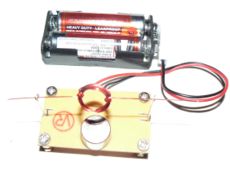
This tutorial will teach you how to build a very simple DC motor. | |||
</onlyinclude> | |||
== Step 1: Collect all components == | == Step 1: Collect all components == | ||
| Line 11: | Line 23: | ||
* Four numbers of screws and standoffs. | * Four numbers of screws and standoffs. | ||
* A small rectangular piece of PCB. | * A small rectangular piece of PCB. | ||
[[Image:Diy motor 1.jpg|300px]] | |||
Apart from these components, you would also need the following tools: | |||
* Hacksaw | |||
* Wire snipper/cutter | |||
* Solder Iron and solder | |||
* Sharp knife | |||
* Drill bits: 3-mm and 1-mm | |||
* A Used 'AAA' size battery to wind the coil. | |||
== Step 2: Drill the PCB == | == Step 2: Drill the PCB == | ||
As shown in the photograph below, drill the PCB corners with 3 mm drill bit for the screws and standoffs. | As shown in the photograph below, drill the PCB corners with 3 mm drill bit for the screws and standoffs. | ||
[[Image:Diy motor 2.jpg|300px]] | |||
== Step 3: Hacksaw sides of the PCB == | == Step 3: Hacksaw sides of the PCB == | ||
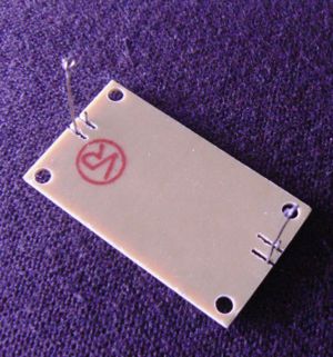
Using a hacksaw, make two 3-mm deep incisions on opposite sides of the PCB as shown in the photograph. | Using a hacksaw, make two 3-mm deep incisions on opposite sides of the PCB as shown in the photograph. | ||
[[Image:Diy motor 3.jpg|300px]] | |||
== Step 4: Prepare the Motor Contacts I == | == Step 4: Prepare the Motor Contacts I == | ||
Using the small drill bit (I used a 2-mm drill bit) bend the hookup wire to make a loop as shown the photograph below. | Using the small drill bit (I used a 2-mm drill bit) bend the hookup wire to make a loop as shown the photograph below. | ||
[[Image:Diy motor 4.jpg|300px]] | |||
== Step 5: Prepare the Motor Contacts II == | == Step 5: Prepare the Motor Contacts II == | ||
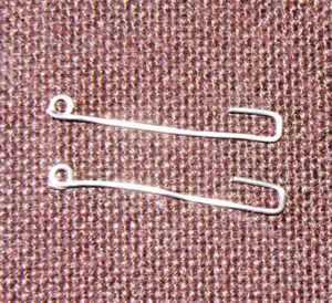
Cut each hookup wire to about an inch in length. Make U shaped bends at the other end of the wires as shown in the photograph. | Cut each hookup wire to about an inch in length. Make U shaped bends at the other end of the wires as shown in the photograph. | ||
[[Image:Diy motor 5.jpg|300px]] | |||
== Step 6: Prepare the PCB == | == Step 6: Prepare the PCB == | ||
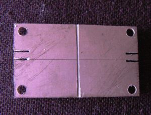
Using a hacksaw, separate the copper foil in two as shown in the photograph below. | Using a hacksaw, separate the copper foil in two as shown in the photograph below. | ||
[[Image:Diy motor 6.jpg|300px]] | |||
== Step 7: Solder the Motor Terminals to the PCB == | == Step 7: Solder the Motor Terminals to the PCB == | ||
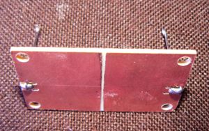
As shown in the photograph below, solder the hookup wire to the PCB through the incisions made in the PCB. | As shown in the photograph below, solder the hookup wire to the PCB through the incisions made in the PCB. | ||
[[Image:Diy motor 7.jpg|300px]] | |||
[[Image:Diy motor 8.jpg|300px]] | |||
== Step 8: Prepare the Motor Coil I == | == Step 8: Prepare the Motor Coil I == | ||
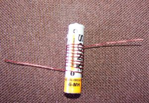
Use a AAA sized battery as a former, to wind 10 turns of 26-SWG magnet wire as shown the photograph below. Leave about 2 inches of length of wire at both the ends. | Use a AAA sized battery as a former, to wind 10 turns of 26-SWG magnet wire as shown the photograph below. Leave about 2 inches of length of wire at both the ends. | ||
[[Image:Diy motor 9.jpg|300px]] | |||
== Step 9: Prepare the Motor Coil II == | == Step 9: Prepare the Motor Coil II == | ||
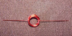
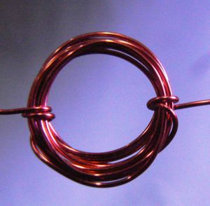
Remove the coil from the former and loop the ends of the wires around the coil a few times as shown in the photograph below. Make sure that the two loops are exactly 180 degrees apart and that the coil is balanced about these loops. | Remove the coil from the former and loop the ends of the wires around the coil a few times as shown in the photograph below. Make sure that the two loops are exactly 180 degrees apart and that the coil is balanced about these loops. | ||
== Step 10: Prepare the Motor Coil III | [[Image:Diy motor 10.jpg|300px]] | ||
[[Image:Diy motor 11.jpg|300px]] | |||
== Step 10: Prepare the Motor Coil III == | |||
Use an Exacto knife or any other knife with sharp edge to scrape off part of the insulation from the two ends of the coil along the entire length of the wire. Do not remove the insulation of the loop part of the wire. Do not remove all the insulation. | Use an Exacto knife or any other knife with sharp edge to scrape off part of the insulation from the two ends of the coil along the entire length of the wire. Do not remove the insulation of the loop part of the wire. Do not remove all the insulation. | ||
[[Image:Diy motor 12.jpg|300px]] | |||
The illustration below shows how to remove the insulation from the two ends of the loop. The black portion shows the part of the wire where the insulation has been removed. | The illustration below shows how to remove the insulation from the two ends of the loop. The black portion shows the part of the wire where the insulation has been removed. | ||
[[Image:Diy motor 13.jpg|300px]] | |||
== Step 11: Mount the screws on the PCB and Glue the magnet == | == Step 11: Mount the screws on the PCB and Glue the magnet == | ||
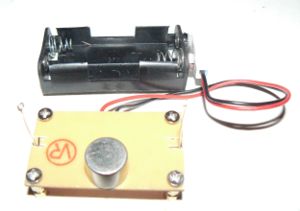
As shown in the photograph below, mount the four screws and standoffs on the PCB and attach the magnet in the middle of the PCB using a drop of quick setting adhesive. | As shown in the photograph below, mount the four screws and standoffs on the PCB and attach the magnet in the middle of the PCB using a drop of quick setting adhesive. | ||
[[Image:Diy motor 14.jpg|300px]] | |||
== Step 12: Mount the coil and flick it! == | == Step 12: Mount the coil and flick it! == | ||
| Line 49: | Line 95: | ||
Have fun! | Have fun! | ||
<onlyinclude> | |||
[[Image:Diy motor 15.jpg|300px]] | |||
</onlyinclude> | |||
== See also == | |||
* [http://www.simplemotor.com/ Simplemotor.com has a similar tutorial] | |||
[[Category:Tutorials]] | |||
Latest revision as of 16:02, 11 September 2008
| Tutorial | |
 DIY Motor in 12 Easy Steps | |
| Author: | Dhananjay V. Gadre |
| Materials: | See text |
| Tools: | See text |
| Difficulty: | Easy |
| Estimated time: | 60-90 mins |
This tutorial will teach you how to build a very simple DC motor.
Step 1: Collect all components
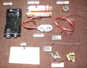
Collect all the components as shown in the picture below. You will need
- Two Alkaline 1.5V batteries (even one battery will do). AA or AAA Size.
- Battery Holder (AA or AAA Size depending upon your battery) with connector
- Rare Earth Magnet (Size not critical). I used a magnet with 10 mm dia and 10 mm length.
- A feet of Magnet wire, 26 SWG
- Two pieces of Hookup wire 24SWG, 6 inch length each.
- Four numbers of screws and standoffs.
- A small rectangular piece of PCB.
Apart from these components, you would also need the following tools:
- Hacksaw
- Wire snipper/cutter
- Solder Iron and solder
- Sharp knife
- Drill bits: 3-mm and 1-mm
- A Used 'AAA' size battery to wind the coil.
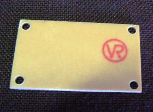
Step 2: Drill the PCB
As shown in the photograph below, drill the PCB corners with 3 mm drill bit for the screws and standoffs.
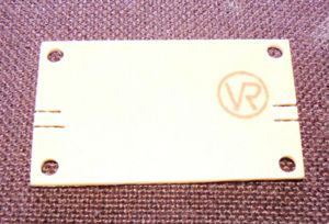
Step 3: Hacksaw sides of the PCB
Using a hacksaw, make two 3-mm deep incisions on opposite sides of the PCB as shown in the photograph.
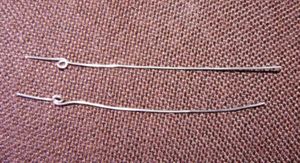
Step 4: Prepare the Motor Contacts I
Using the small drill bit (I used a 2-mm drill bit) bend the hookup wire to make a loop as shown the photograph below.
Step 5: Prepare the Motor Contacts II
Cut each hookup wire to about an inch in length. Make U shaped bends at the other end of the wires as shown in the photograph.
Step 6: Prepare the PCB
Using a hacksaw, separate the copper foil in two as shown in the photograph below.
Step 7: Solder the Motor Terminals to the PCB
As shown in the photograph below, solder the hookup wire to the PCB through the incisions made in the PCB.
Step 8: Prepare the Motor Coil I
Use a AAA sized battery as a former, to wind 10 turns of 26-SWG magnet wire as shown the photograph below. Leave about 2 inches of length of wire at both the ends.
Step 9: Prepare the Motor Coil II
Remove the coil from the former and loop the ends of the wires around the coil a few times as shown in the photograph below. Make sure that the two loops are exactly 180 degrees apart and that the coil is balanced about these loops.
Step 10: Prepare the Motor Coil III
Use an Exacto knife or any other knife with sharp edge to scrape off part of the insulation from the two ends of the coil along the entire length of the wire. Do not remove the insulation of the loop part of the wire. Do not remove all the insulation.
The illustration below shows how to remove the insulation from the two ends of the loop. The black portion shows the part of the wire where the insulation has been removed.
Step 11: Mount the screws on the PCB and Glue the magnet
As shown in the photograph below, mount the four screws and standoffs on the PCB and attach the magnet in the middle of the PCB using a drop of quick setting adhesive.
Step 12: Mount the coil and flick it!
As shown in the photograph below, mount the coil in the loops of the hookup wire and install the batteries in the battery holder. If the coil does not start rotating on its own, flick it gently with a finger and see it rev up and continue to rotate.
Have fun!
