I downloaded [AVR Data sheet for Attiny45] from [http://www.atmel.com/dyn/products/product_card.asp?PN=ATtiny45 Atmel]
I downloaded [AVR Data sheet for Attiny45] from [http://www.atmel.com/dyn/products/product_card.asp?PN=ATtiny45 Atmel]
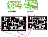
I take a look at codes from [http://fab.cba.mit.edu/about/fab/ Fab Hello World page] specially at hello.speaker.45.pwm.asm and hello.step.45.asm
==AVR ==
==AVR ==
Line 49:
Line 52:
==Alternate the code ==
==Alternate the code ==
Define variablbe.
Define variablbe.
.def sensor_pin = PB3 ; we call pin PB3 a sensor pin
.equ sensor_pin = PB3 ; we call pin PB3 a sensor pin
def charge_pin = PB4 ; PB4 is our charge pin
.equ charge_pin = PB4 ; PB4 is our charge pin
.def sensor_value_high = R23 ; temporary storage for sensor value (here we store our sensor values (because we have 10 bit value, here we have the higher value)
.def sensor_value_high = R23 ; temporary storage for sensor value (here we store our sensor values (because we have 10 bit value, here we have the higher value)
.def sensor_value_low = R24 ; temporary storage for sensor value (here we store our sensor values (because we have 10 bit value, here we have the lower value)
.def sensor_value_low = R24 ; temporary storage for sensor value (here we store our sensor values (because we have 10 bit value, here we have the lower value)
Revision as of 11:57, 30 March 2010
Hello Speaker and Hello Step
I decided to try to start making the board, by drawing it in Eagle.
I downloaded and installed the Eagle Freeversion from Cad Soft USA
I downloaded [AVR Data sheet for Attiny45] from Atmel
I take a look at codes from Fab Hello World page specially at hello.speaker.45.pwm.asm and hello.step.45.asm
AVR
SBI -> Set Bit in I/O Register
CBI -> Clear Bit in I/O Register
LDI -> Load Immediate
BRNE-> Branch if Not Equal
First we made some experiments
Open AVR studio
File New Project
Write .asm code
include "tn44def.inc";
sbi DDRA, 0;
ldi R18, 10;
LoopA:
	sbi PORTA, 0;
	ldi R19, 15;
	Loop2:
		dec R19;
		brne Loop2;
		cbi PORTA, 0;
		ldi R19, 20;
		Loop3:
			dec R19;
			brne Loop3
  	dec R18;
  	brne LoopA;
Build and Run
Step into
Alternate the code
Define variablbe.
.equ sensor_pin = PB3 ; we call pin PB3 a sensor pin
.equ charge_pin = PB4 ; PB4 is our charge pin
.def sensor_value_high = R23	; temporary storage for sensor value  (here we store our sensor values (because   we have 10 bit value, here we have the higher value)
.def sensor_value_low = R24	; temporary storage for sensor value (here we store our sensor values (because  we have 10 bit value, here we have the lower value)
; set Chargepin to output
   ;
   cbi PORTB, charge_pin (the charge_pin is set to low)
   sbi DDRB, charge_pin ( charge pin is output
Next we define measuring method.
   ; init A/D
   ;
   cbi ADMUX, REFS2 ; use Vcc as reference
   cbi ADMUX, REFS1 ; "
   cbi ADMUX, REFS0 ; "
   cbi ADMUX, ADLAR ; right-adjust result
   cbi ADMUX, MUX3 ; set MUX to ADC2 (PB4) here we decide what pin we use for measurement
   cbi ADMUX, MUX2 ; "
   sbi ADMUX, MUX1 ; "
   cbi ADMUX, MUX0 ; "
   sbi ADCSRA, ADEN ; enable A/D
   cbi ADCSRA, ADPS2 ; set prescaler to /2 (here we define at what speed we measure)
   cbi ADCSRA, ADPS1 ; "
   cbi ADCSRA, ADPS0 ; "