**It should be musical instrument, in the way that the board develops sounds on the speaker when I move copper foils towards one another.
==Design==
==The schematic and board layout==
I decided to try to start to draw the board in Eagle.
I decided to try to start to draw the board in Eagle.
* I downloaded and installed the Eagle Freeversion from [http://www.cadsoftusa.com/download.htm Cad Soft USA]
Then I tried to use Inkscape to sketch what I wanted it to do.
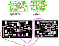
[[Image:Step speaker test.png|thumb|200 px]]
* I downloaded and installed the Eagle Free version from [http://www.cadsoftusa.com/download.htm Cad Soft USA]
* I downloaded and copied Neils library from [http://fab.cba.mit.edu/about/fab/dist/ng.lbr http://fab.cba.mit.edu/about/fab/dist/ng.lbr] to the folder where other libraries are.
* I downloaded and copied Neils library from [http://fab.cba.mit.edu/about/fab/dist/ng.lbr http://fab.cba.mit.edu/about/fab/dist/ng.lbr] to the folder where other libraries are.
* First I drew [http://fab.cba.mit.edu/about/fab/hello/speaker/hello.speaker.45.MTA.cad hello.speaker.45.MTA].
* First I drew [http://fab.cba.mit.edu/about/fab/hello/speaker/hello.speaker.45.MTA.cad hello.speaker.45.MTA].
*The results were not sufficient, since I had some trouble making the routes.
*The results were not sufficient, since I had some trouble making the routes.
Then I tried to use Inkscape to sketch what I wanted it to do.
[[Image:Step speaker test.png|thumb|200 px]]
== Programming the board==
== Programming the board==
First I have to decide the function of the board.
*The function should be:
**Make musical instrument with it, so that the board develops sounds on the speaker when I move copper foils towards one another.
* Then I have to make program for the board.
* Then I have to make program for the board.
Line 25:
Line 27:
I take a look at codes from [http://fab.cba.mit.edu/about/fab/ Fab Hello World page] specially at hello.speaker.45.pwm.asm and hello.step.45.asm
I take a look at codes from [http://fab.cba.mit.edu/about/fab/ Fab Hello World page] specially at hello.speaker.45.pwm.asm and hello.step.45.asm
Define variablbe.
.equ sensor_pin = PB3 ; we call pin PB3 a sensor pin
.equ charge_pin = PB4 ; PB4 is our charge pin
.def sensor_value_high = R23	; temporary storage for sensor value  (here we store our sensor values (because   we have 10 bit value, here we have the higher value)
.def sensor_value_low = R24	; temporary storage for sensor value (here we store our sensor values (because  we have 10 bit value, here we have the lower value)
; set Chargepin to output
   ;
   cbi PORTB, charge_pin (the charge_pin is set to low)
   sbi DDRB, charge_pin ( charge pin is output
Next we define measuring method.
   ; init A/D
   ;
   cbi ADMUX, REFS2 ; use Vcc as reference
   cbi ADMUX, REFS1 ; "
   cbi ADMUX, REFS0 ; "
   cbi ADMUX, ADLAR ; right-adjust result
   cbi ADMUX, MUX3 ; set MUX to ADC2 (PB4) here we decide what pin we use for measurement
   cbi ADMUX, MUX2 ; "
   sbi ADMUX, MUX1 ; "
   cbi ADMUX, MUX0 ; "
   sbi ADCSRA, ADEN ; enable A/D
   cbi ADCSRA, ADPS2 ; set prescaler to /2 (here we define at what speed we measure)
   cbi ADCSRA, ADPS1 ; "
   cbi ADCSRA, ADPS0 ; "
Mistakes that we made:
First we defined PB4 as a sensor pin and a charge pin, we fixed that by defining PB3 as a charge pin and PB4 as a sensor pin.
Then we started to get some response from the sensor.
At first we only used lower value.
;
; hello.speaker.45.pwm.asm
;
; software PWM speaker hello-world program
;
; Neil Gershenfeld MIT CBA 8/2/07
;
; (c) Massachusetts Institute of Technology 2007
; Permission granted for experimental and personal use;
; license for commercial sale available from MIT.
;

 .include "tn45def.inc"

 .equ mosfet_pin = PB1 ; MOSFET pin
.equ max_pwm = 20 ; maximum PWM on value
.equ pwm_length = 40 ; PWM loop length
.equ sensor_pin = PB4	; we call pin PB4 a sensor pin
.equ charge_pin = PB3	; PB3 is our charge pin


.def temp = R16	; temporary storage
.def temp1 = R17 ; temporary storage
.def pwm = R18 ; PWM value
.def pwm_count = R19 ; PWM counter
.def pwm_cycle = R20 ; PWM cycle count
.def pwm_cycle_count = R21 ; number of PWM cycles per audio cycle
.def cycle_count = R22 ; audio cycle count
.def sensor_value_high = R23	; temporary storage for sensor value
.def sensor_value_low = R24	; temporary storage for sensor value

.cseg
.org 0
rjmp reset

;
; main program
;
reset:
   ;
   ; initialization
   ;
   ; set clock divider to /1
   ;
   ldi temp, (1 << CLKPCE)
   ldi temp1, (0 << CLKPS3) | (0 << CLKPS2) | (0 << CLKPS1) | (0 << CLKPS0)
   out CLKPR, temp
   out CLKPR, temp1
   ;
   ; set stack pointer to top of RAM
   ;
   ldi temp, high(RAMEND)
   out SPH, temp
   ldi temp, low(RAMEND)
   out SPL, temp
   ;
   ; set MOSFET to output
   ;
   cbi PORTB, mosfet_pin
   sbi DDRB, mosfet_pin
   ;

 ; set Chargepin to output
   ;
   cbi PORTB, charge_pin
   sbi DDRB, charge_pin

;
   ; init A/D
  ;
   cbi ADMUX, REFS2 ; use Vcc as reference
   cbi ADMUX, REFS1 ; "
   cbi ADMUX, REFS0 ; "
   cbi ADMUX, ADLAR ; right-adjust result
   cbi ADMUX, MUX3 ; set MUX to ADC2 (PB4) here we decide what pin we use for measurement
   cbi ADMUX, MUX2 ; "
   sbi ADMUX, MUX1 ; "
   cbi ADMUX, MUX0 ; "
   sbi ADCSRA, ADEN ; enable A/D
   cbi ADCSRA, ADPS2 ; set prescaler to /2 (here we define at what speed we measure)
   cbi ADCSRA, ADPS1 ; "
   cbi ADCSRA, ADPS0 ; "


   ; infinite main loop
   ;
   main_loop:

	;first we fetch one measurement

	 ; read response
         ;
         sbi ADCSRA, ADSC ; start conversion
         adloopup:
            sbic ADCSRA, ADSC ; loop until complete
            rjmp adloopup
         ;
         ; save conversion
         ;
         in sensor_value_low, ADCL ; get low byte from sensor
         in sensor_value_high, ADCH ; get high byte from sensor


      ldi pwm_cycle_count, 5
      frequency_loop:
         ; we will not use this line ldi cycle_count, sensor_value_low
		 mov cycle_count, sensor_value_low
         cycle_count_loop:
            ldi pwm, max_pwm
           cycle_loop:
                mov pwm_cycle, pwm_cycle_count
               pwm_loop:
                  mov pwm_count, pwm
                  sbi PORTB, mosfet_pin
                  pwm_on_loop:
                     dec pwm_count
                     brne pwm_on_loop
                  ldi pwm_count, pwm_length
                  sub pwm_count, pwm
                  cbi PORTB, mosfet_pin
                  pwm_off_loop:
                     dec pwm_count
                     brne pwm_off_loop
                  dec pwm_cycle
                  brne pwm_loop
               dec pwm
               brne cycle_loop
             dec cycle_count
             brne cycle_count_loop
          dec pwm_cycle_count
          brne frequency_loop
       rjmp main_loop