User:Frosti/Sensors, Actuators, and Displays: Difference between revisions
| Line 41: | Line 41: | ||
*Turn off all layers except the routes, go to File-> Export -> Browse, .png, 500 dpi. | *Turn off all layers except the routes, go to File-> Export -> Browse, .png, 500 dpi. | ||
*Now turn off all layers except the frame, and go to File-> Export -> Browse, .png, 500 dpi. | *Now turn off all layers except the frame, and go to File-> Export -> Browse, .png, 500 dpi. | ||
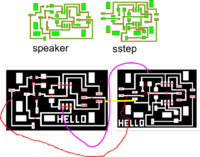
[[Image:Speaker 20100330 with | [[Image:Speaker 20100330 with notes3.png|thumb|300px]] | ||
==Physical Fabrication == | ==Physical Fabrication == | ||
Revision as of 14:39, 5 April 2010
Goal
The goal is to make theremin with our Fab Lab equipment and inventory.
But the still the project is not fully ready. We use variable resistor to change the speed of music.
<video type="youtube">PTvFEJ0FUio</video>
Steps
Desired function of the circuit board
First I have to decide the function of the board.
- The function should be:
- It should be musical instrument, in the way that the board develops sounds on the speaker when I move copper foils towards one another.
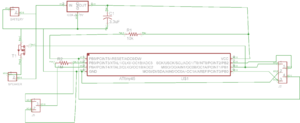
The schematic and board layout
I tried to use Inkscape to sketch what I wanted it to do. Then I decided to try to start to draw the board in Eagle.

- I downloaded and installed the Eagle Free version from Cad Soft USA
- I downloaded and copied Neils library from http://fab.cba.mit.edu/about/fab/dist/ng.lbr to the folder where other libraries are.
- First I drew hello.speaker.45.MTA.
- Before starting to draw, remember to change the grid to 0.025 inches. That will help a lot later on.
- We have two views
- Schematic
- Board
- I added some new components
- Add
- Resistor 1 Mega Ohm
- MTA connector 3 pin
- Add

Making the Board layout

At first I had some troubles making the routes.
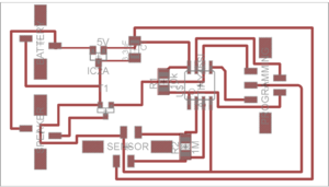
- Then I used Route button and connected from one component to another.
- To change location of the component label, we can go to Board layout and right click on the components and select Smash, then we are able to move the text label.
- When the routes are ready you can go to View -> Display/hide layers and select what layers you want to see.
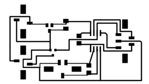
- Turn off all layers except the routes, go to File-> Export -> Browse, .png, 500 dpi.
- Now turn off all layers except the frame, and go to File-> Export -> Browse, .png, 500 dpi.

Physical Fabrication
We make the board on Modela.
- Mistakes that we made originally, we changed X min and Y min like we should do, but we also changed X width and Height. But we shouldn't have to change X width and Height.
- IC1 = ATtiny45_SOIC('IC1\nt45')
- IC2 = regulator_SOT23('IC2\n5V')
- R1 = R_1206('R1\n10k')
- C1 = C_1206('C1\n3.3uF')
- J1 = MTA_power('J1')
- J2 = MTA_ICP('J2')
- J3 = MTA_2('J3')
- T1 = NMOSFET_SOT23('T1: N')
- Speaker and connector
- Battery (power), cable, and connector
- 10 k Ohm variable resistor
Programming the board
- Then I have to make program for the board.
- I downloaded [AVR Data sheet for Attiny45] from Atmel
I take a look at codes from Fab Hello World page specially at hello.speaker.45.pwm.asm and hello.step.45.asm
Some AVR Instructions
- SBI -> Set Bit in I/O Register
- CBI -> Clear Bit in I/O Register
- LDI -> Load Immediate
- BRNE-> Branch if Not Equal
First we made some experiments
- Open AVR studio
- File New Project
- Write .asm code
- Build and Run
- Step into
First we look at our board
- We look at our hello.speaker.45.cad board and check if we have some available pins to use.
- We see that we have PB3 and PB4 available.
- We can now start to check the code.
Lets use hello.speaker.45.pwm.asm
We download hello.speaker.45.pwm.asm and change the code.
We use also a little bit of hello.step.45.asm program.
Alternate the code
Define variablbe. .equ sensor_pin = PB3 ; we call pin PB3 a sensor pin .equ charge_pin = PB4 ; PB4 is our charge pin
.def sensor_value_high = R23	; temporary storage for sensor value  (here we store our sensor values (because   we have 10 bit value, here we have the higher value)
.def sensor_value_low = R24	; temporary storage for sensor value (here we store our sensor values (because  we have 10 bit value, here we have the lower value)
; set Chargepin to output
   ;
   cbi PORTB, charge_pin (the charge_pin is set to low)
   sbi DDRB, charge_pin ( charge pin is output
Next we define measuring method.
   ; init A/D
   ;
   cbi ADMUX, REFS2 ; use Vcc as reference
   cbi ADMUX, REFS1 ; "
   cbi ADMUX, REFS0 ; "
   cbi ADMUX, ADLAR ; right-adjust result
   cbi ADMUX, MUX3 ; set MUX to ADC2 (PB4) here we decide what pin we use for measurement
   cbi ADMUX, MUX2 ; "
   sbi ADMUX, MUX1 ; "
   cbi ADMUX, MUX0 ; "
   sbi ADCSRA, ADEN ; enable A/D
   cbi ADCSRA, ADPS2 ; set prescaler to /2 (here we define at what speed we measure)
   cbi ADCSRA, ADPS1 ; "
   cbi ADCSRA, ADPS0 ; "
Mistakes that we made:
- First we defined PB4 as a sensor pin and a charge pin, we fixed that by defining PB3 as a charge pin and PB4 as a sensor pin.
- Then we started to get some response from the sensor.
- At first we only used lower value.
;==First version==
;
; hello.speaker.45.pwm.asm
;
; software PWM speaker hello-world program
;
; Neil Gershenfeld MIT CBA 8/2/07
;
; (c) Massachusetts Institute of Technology 2007
; Permission granted for experimental and personal use;
; license for commercial sale available from MIT.
;

 .include "tn45def.inc"

 .equ mosfet_pin = PB1 ; MOSFET pin
.equ max_pwm = 20 ; maximum PWM on value
.equ pwm_length = 40 ; PWM loop length
.equ sensor_pin = PB4	; we call pin PB4 a sensor pin
.equ charge_pin = PB3	; PB3 is our charge pin


.def temp = R16	; temporary storage
.def temp1 = R17 ; temporary storage
.def pwm = R18 ; PWM value
.def pwm_count = R19 ; PWM counter
.def pwm_cycle = R20 ; PWM cycle count
.def pwm_cycle_count = R21 ; number of PWM cycles per audio cycle
.def cycle_count = R22 ; audio cycle count
.def sensor_value_high = R23	; temporary storage for sensor value
.def sensor_value_low = R24	; temporary storage for sensor value

.cseg
.org 0
rjmp reset

;
; main program
;
reset:
   ;
   ; initialization
   ;
   ; set clock divider to /1
   ;
   ldi temp, (1 << CLKPCE)
   ldi temp1, (0 << CLKPS3) | (0 << CLKPS2) | (0 << CLKPS1) | (0 << CLKPS0)
   out CLKPR, temp
   out CLKPR, temp1
   ;
   ; set stack pointer to top of RAM
   ;
   ldi temp, high(RAMEND)
   out SPH, temp
   ldi temp, low(RAMEND)
   out SPL, temp
   ;
   ; set MOSFET to output
   ;
   cbi PORTB, mosfet_pin
   sbi DDRB, mosfet_pin
   ;

 ; set Chargepin to output
   ;
   cbi PORTB, charge_pin
   sbi DDRB, charge_pin

;
   ; init A/D
  ;
   cbi ADMUX, REFS2 ; use Vcc as reference
   cbi ADMUX, REFS1 ; "
   cbi ADMUX, REFS0 ; "
   cbi ADMUX, ADLAR ; right-adjust result
   cbi ADMUX, MUX3 ; set MUX to ADC2 (PB4) here we decide what pin we use for measurement
   cbi ADMUX, MUX2 ; "
   sbi ADMUX, MUX1 ; "
   cbi ADMUX, MUX0 ; "
   sbi ADCSRA, ADEN ; enable A/D
   cbi ADCSRA, ADPS2 ; set prescaler to /2 (here we define at what speed we measure)
   cbi ADCSRA, ADPS1 ; "
   cbi ADCSRA, ADPS0 ; "


   ; infinite main loop
   ;
   main_loop:

	;first we fetch one measurement

	 ; read response
         ;
         sbi ADCSRA, ADSC ; start conversion
         adloopup:
            sbic ADCSRA, ADSC ; loop until complete
            rjmp adloopup
         ;
         ; save conversion
         ;
         in sensor_value_low, ADCL ; get low byte from sensor
         in sensor_value_high, ADCH ; get high byte from sensor


      ldi pwm_cycle_count, 5
      frequency_loop:
         ; we will not use this line ldi cycle_count, sensor_value_low
		 mov cycle_count, sensor_value_low
         cycle_count_loop:
            ldi pwm, max_pwm
           cycle_loop:
                mov pwm_cycle, pwm_cycle_count
               pwm_loop:
                  mov pwm_count, pwm
                  sbi PORTB, mosfet_pin
                  pwm_on_loop:
                     dec pwm_count
                     brne pwm_on_loop
                  ldi pwm_count, pwm_length
                  sub pwm_count, pwm
                  cbi PORTB, mosfet_pin
                  pwm_off_loop:
                     dec pwm_count
                     brne pwm_off_loop
                  dec pwm_cycle
                  brne pwm_loop
               dec pwm
               brne cycle_loop
             dec cycle_count
             brne cycle_count_loop
          dec pwm_cycle_count
          brne frequency_loop
       rjmp main_loop
Code of second version
This is second version of our program and now it changes the speed of the music depending on how we turn the variable resistor.
	;
	; hello.speaker.45.pwm.asm
	;
	; software PWM speaker hello-world program
	;
	; Neil Gershenfeld MIT CBA 8/2/07
	;
	; (c) Massachusetts Institute of Technology 2007
	; Permission granted for experimental and personal use;
	; license for commercial sale available from MIT.
	; changed by Fab Academy students in Vestmannaeyjar

	.include "tn45def.inc"

	.equ mosfet_pin = PB1 ; MOSFET pin
	.equ max_pwm = 20 ; maximum PWM on value
	.equ pwm_length = 40 ; PWM loop length
	.equ sensor_pin = PB4    ; we call pin PB4 a sensor pin
	.equ charge_pin = PB3    ; PB3 is our charge pin


	.def temp = R16    ; temporary storage
	.def temp1 = R17 ; temporary storage
	.def pwm = R18 ; PWM value
	.def pwm_count = R19 ; PWM counter
	.def pwm_cycle = R20 ; PWM cycle count
	.def pwm_cycle_count = R21 ; number of PWM cycles per audio cycle
	.def cycle_count = R22 ; audio cycle count
	.def sensor_value_high = R23    ; temporary storage for sensor value
	.def sensor_value_low = R24    ; temporary storage for sensor value
	.DEF rd1l = R0 ; LSB 16-bit-number to be divided
	.DEF rd1h = R1 ; MSB 16-bit-number to be divided
	.DEF rd1u = R2 ; interim register
	.DEF rd2 = R3 ; 8-bit-number to divide with
	.DEF rel = R4 ; LSB result
	.DEF reh = R5 ; MSB result
	.DEF rmp = R25; multipurpose register for loading


	.cseg
	.org 0
	rjmp reset

	;
	; main program
	;
	reset:
	   ;
	   ; initialization
	   ;
	   ; set clock divider to /1
	   ;
	   ldi temp, (1 << CLKPCE)
	   ldi temp1, (0 << CLKPS3) | (0 << CLKPS2) | (0 << CLKPS1) | (0 << CLKPS0)
	   out CLKPR, temp
	   out CLKPR, temp1
	   ;
	   ; set stack pointer to top of RAM
	   ;
	   ldi temp, high(RAMEND)
	   out SPH, temp
	   ldi temp, low(RAMEND)
	   out SPL, temp
	   ;
	   ; set MOSFET to output
	   ;
	   cbi PORTB, mosfet_pin
	   sbi DDRB, mosfet_pin
	   ;

	 ; set Chargepin to output
	   ;
	   cbi PORTB, charge_pin
	   sbi DDRB, charge_pin

	;
	   ; init A/D
	   ;
	   cbi ADMUX, REFS2 ; use Vcc as reference
	   cbi ADMUX, REFS1 ; "
	   cbi ADMUX, REFS0 ; "
	   cbi ADMUX, ADLAR ; right-adjust result
	   cbi ADMUX, MUX3 ; set MUX to ADC2 (PB4) here we decide what pin we use for measurement
	   cbi ADMUX, MUX2 ; "
	   sbi ADMUX, MUX1 ; "
	   cbi ADMUX, MUX0 ; "
	   sbi ADCSRA, ADEN ; enable A/D
	   cbi ADCSRA, ADPS2 ; set prescaler to /2 (here we define at what speed we measure)
	   cbi ADCSRA, ADPS1 ; "
	   cbi ADCSRA, ADPS0 ; "


	   ; infinite main loop
	   ;
	   main_loop:

	    ;first we fetch one measurement

	     ; read response
	         ;
	         sbi ADCSRA, ADSC ; start conversion
	         adloopup:
	            sbic ADCSRA, ADSC ; loop until complete
	            rjmp adloopup
	         ;
	         ; save conversion


	         ;
	         in sensor_value_low, ADCL ; get low byte from sensor
	         in sensor_value_high, ADCH ; get high byte from sensor

	            ;Here we divide the results from the sensor Devision starts
	        ; Load the test numbers to the appropriate registers
	        ;

	            mov rd1h,sensor_value_high ; use the high sensor value
	            mov rd1l,sensor_value_low ; use the low sensor value
	            ldi rmp,0x4 ; 0x4 to be divided with
	            mov rd2,rmp
	        ;
	        ; Divide rd1h:rd1l by rd2
	        ;
	        div8:
	            clr rd1u ; clear interim register
	            clr reh ; clear result (the result registers
	            clr rel ; are also used to count to 16 for the
	            inc rel ; division steps, is set to 1 at start)
	        ;
	        ; Here the division loop starts
	        ;
	        div8a:
	            clc ; clear carry-bit
	            rol rd1l ; rotate the next-upper bit of the number
	            rol rd1h ; to the interim register (multiply by 2)
	            rol rd1u
	            brcs div8b ; a one has rolled left, so subtract
	            cp rd1u,rd2 ; Division result 1 or 0?
	            brcs div8c ; jump over subtraction, if smaller
	        div8b:
	            sub rd1u,rd2; subtract number to divide with
	            sec ; set carry-bit, result is a 1
	            rjmp div8d ; jump to shift of the result bit
	        div8c:
	            clc ; clear carry-bit, resulting bit is a 0
	        div8d:
	            rol rel ; rotate carry-bit into result registers
	            rol reh
	            brcc div8a ; as long as zero rotate out of the result
	             ; registers: go on with the division loop
	        ; End of the division reached

	      ldi pwm_cycle_count, 5
	      frequency_loop:
	         ; we will not use this line ldi cycle_count, sensor_value_low
	         mov cycle_count, rel ; we use the result from the devision, lower value
	         cycle_count_loop:
	            ldi pwm, max_pwm
	            cycle_loop:
	               mov pwm_cycle, pwm_cycle_count
	               pwm_loop:
	                  mov pwm_count, pwm
	                  sbi PORTB, mosfet_pin
	                  pwm_on_loop:
	                     dec pwm_count
	                     brne pwm_on_loop
	                  ldi pwm_count, pwm_length
	                  sub pwm_count, pwm
	                  cbi PORTB, mosfet_pin
	                  pwm_off_loop:
	                     dec pwm_count
	                     brne pwm_off_loop
	                  dec pwm_cycle
	                  brne pwm_loop
	               dec pwm
	               brne cycle_loop
	            dec cycle_count
	            brne cycle_count_loop
	         dec pwm_cycle_count
	         brne frequency_loop
	      rjmp main_loop
Using AVR Studio
- Build and Run
- Create .hex file
- Attention -> Remember to unplug the speaker before you program the micro controler.
- Load program to circuit board.
- avrdude -p t45 -c bsd -U flash:w:file.hex
Links
Simple test program=
include "tn44def.inc";
sbi DDRA, 0;
ldi R18, 10;
LoopA:
	sbi PORTA, 0;
	ldi R19, 15;
	Loop2:
		dec R19;
		brne Loop2;
		cbi PORTA, 0;
		ldi R19, 20;
		Loop3:
			dec R19;
			brne Loop3
  	dec R18;
  	brne LoopA;