Jan Gunster
Overview
Jan Gunster is a Student of Concept Design from The Netherlands and currently on a 4 month internship at the FabLab in Iceland. He is to be reached at JanGunster@gmail.com.
Projects
A project to get local youth more interested
The 3d rotate tool was a concept that used simple parts to create the illusion of a 3d scan.
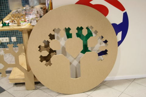
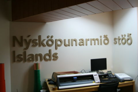
Together with Frosti I made some improvements in and around the FabLab to give it more of an identity and overall a more cohesive feel. For this I used the Vinyl cutter and lots and lots of sticker material.
Fab Academy
Assignment one
I entered the Fab Academy late, so the first assignment I started working on was making press fits. I produced 3 different designs, each with its own problems and challenges.
Jet Fighter
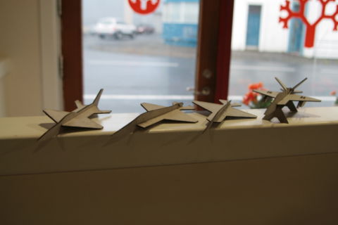
For this press fit, shaped like a jet fighter, I drew inspiration upon the little toy airplanes I had a kid. Where the hull is one piece, and the wings a second piece that fold into each other at a 90 degree angle. My first design was like this. Straightforward and simple. Then I moved on to a design abit more complex. In the second design added tail wings. Here, however, I got some measurements wrong which I fixed in the third version. V.4 was an improvement on the overall design and shape. I also added a landing gear and bombs under the wings. In this version I also added decals. In my 5th and final version I perfected this design.
Eiffel Tower
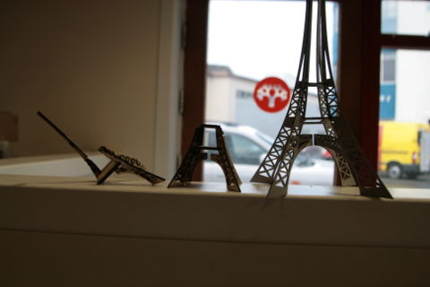
The Eiffel Tower was by far my most challenging design. The idea was simple, four legs each made of one piece, connected at 90 degree angles with two platforms 45 degree angle. The execution was harder, however. The problem was mostly in the material choice. Wood. This proved far too fragile and I had to redesign the entire Eiffel Tower several Times. It kept burning up because the framework was too small. In my fourth and final redesign I opted to increase the size by a factor of two and make the whole thing out of cardboard. This version too proved a failure as the platforms were to small and the legs had a shape that didn't match up. In my fifth and final version I fixed this. I was glad to be done.
Toys
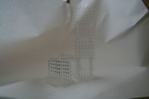
Not happy with my previous designs I opted for a final design that would incorporate everything I had learned. I wanted to make something simple - but varied and complex. I drew inspiration from the Lego's I played with as a kid, as they are essentially press-fits. I wanted to make something similar. One simple design that one could build anything with. This is close to the general philosophy of the FabLab and I liked that. I made squares from cardboard that are similar to your standard press-fit. Only with more gaps. This was a faulty design however. It was limited in building potential and prone to break. So I changed it to Plexiglas, which is harder and stronger. I also made the parts like a grate, with many holes. This version was successful and I am very happy with the result. It would be nice to get some kids to play with this. As a final note I would like to add that I have learned that plexiglass is far from the best material for this, its not flexible and prone to breaking.
Summary
General problems I ran into: Choosing the wrong material, disconnects within software (illustrator /inkscape), making designs too small /too big. The machine not doing what I wanted.
Learned: To operate, calibrate and clean the Laser Cutter. Work in the Inkscape software package. Create and Design my own press-fits.
Assignment two
Circuit Board
The second assignment was about electronics. I'm not that good at making electronics so this was great learning.
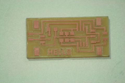
It all started with milling out a would-be circuit board on the milling machine. The second try got it right. For the first try I put the drill too far into the machine, so it couldn't drill deep enough to make a good board.
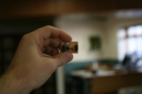
The second part was actually soldering the parts on. This is where the trouble started - I have shaky hands. After about an hour and a half of soldering on my first board I gave up. I had messed up three parts and the board was irrepairable. Part due to my lack of experience in soldering. Sadly, I had to drill out a new circuit board, and decided to get a good night's rest and try again. This proved to be a good decision and the second time I got it right. I made a circuit board!
The third part is programming the circuit board. I quickly ran into problems as I used a 3.3V regulator where I should have used a 5V regulator. I made quick work of it by replacing it quickly and efficiently (unlike other endeavors on said board).
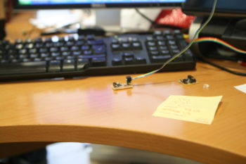
The end product was a circuit board with a cool button that - when pressed - would send some simple text to the computer.
Summary
General problems I ran into: Soldering small parts - not easy. Soldering on wrong parts. Using the wrong technique when removing parts. Using the wrong drill on the milling machine.
Learned: To operate, calibrate and clean the milling machine, and use it to make circuit boards. To solder and identify small parts onto circuit boards. To connect a circuit board to a computer and drop data onto it.
Assignment three
Sign for outside
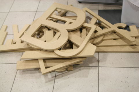
This weeks project started out with the idea to make a sign for outside of the FabLab here. Our FabLaB is hardly recognizable from the outside. The plan was to phrase out the letters on the ShopBot and hang them up. As alway this posed its own set of unique challenges.
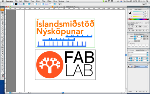
I first started out with a photoshopped image to kind of get a feel for the size. I then opted for a particular design and size and made a design in Illustrator. The reason for the blue lines you see in the screenshot are to preserve spacing once I have the physical product.
The working with the Shopbot went easier then expected and it all pretty much worked for me. I had used the Shopbot before, but never unsupervised. I opted for 17mm MDF because of its aesthetic and its durability, compared to its low price.
The next step here would be to take the letters and hang them outside. After searching for a way to hang them on the wall (which is not as easy as it sounds!) and selecting a color I was basically set to go. However - the outside of our FabLab isn't painted yet! It's still up in scaffolds.
When the outside is finished though, I will have my sweet vengeance in the form of MDF letters.
Assignment four
Casting and molding
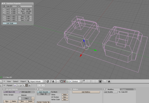
The first step was designing the product in Blender. As you can see above it is a little tetris block cut in half. I made several mistakes; from designing it in reverse, to putting the design sideways so you have 'floating' objects, which with a top-down modeling motion can not be designed. Lesson learned.
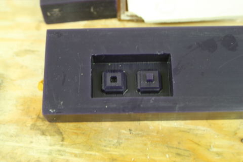
Here you can see what it looks like after it has been fed to the shopbot. Having used the Shopbot many times prior this posed hardly a challenge and worked without a hitch. This was my first 3D object on the Shopbot so that was educational. I learned how to use the 3dpartworks and how to switch tool sizes on the machine.
This is what the actual mold looks like. Made with silicon rubber. I had not done this before so that was fun. I made some mistakes, the most notable one being not making a separator or a way to put the mold together once done. I had to do that by hand. Sloppy. Also I should have added a duct for liquid mold and the air, I had to make those manually. I was lucky the silicon has elasticity so it was not as needed as it would have were it a harder substance.
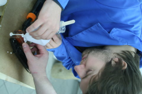
Here you see me pouring the liquid plaster into the mold. As you can see because of the missing air and mold duct I had to kind of pry the silicon apart.
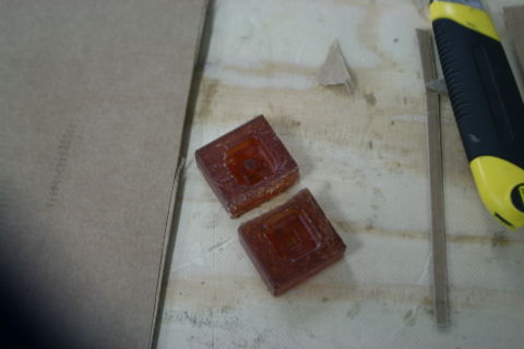
The finished product. Although a little sloppy everything went better than expected.
